 FipLabs
FipDesigner - Design/Control
Overview
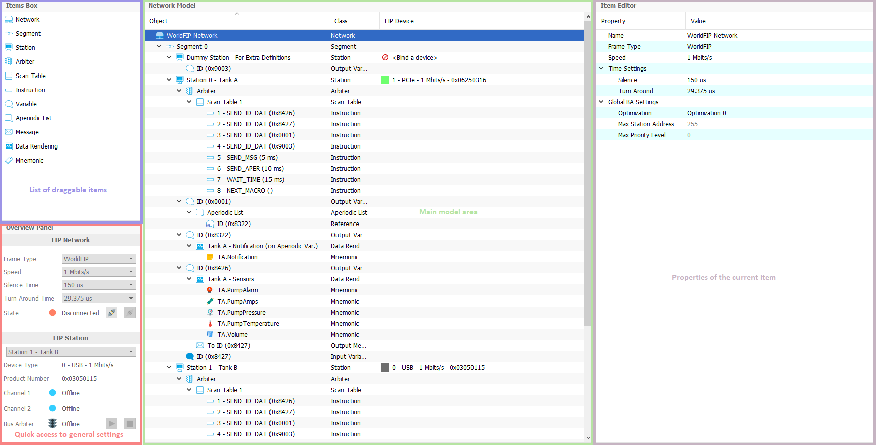
The FipDesigner tab of FipLabs GUI allows to create a model of your FIP network. Through a system of hierarchical items, you can easily build your network.
This model is used to :
- Generate the XML configuration files for each of your FIP stations. These files are used to configure FIP devices of Exoligent for the FipCore library operations.
- Improve data interpretation in the Fipwatcher Tab. With this, it will be possible to perform advanced analysis with the detection of production status for refreshed variables. Instead of only displaying the raw FIP frames, you can also view your own specific mnemonics.
Note : All your XML station files will be saved in the build directory defined in subsection Parameters → Working Directory.
FipLabs - FipDesigner tab - Design Area
FipLabs - FipDesigner tab - Control Area
Design - Network Model
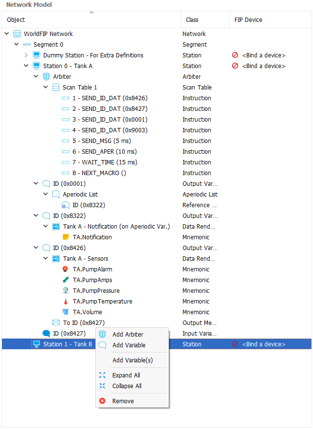
The FIP network is represented using a tree where each item can be dropped on the Network Model view or added by right-clicking on each parent item.
The Items Box panel includes the items that you can drag and drop on the central view to build your network model.
The right view allows you to set in detail the properties of each item of the model.
You can see below the hierarchy of items allowed in the network model:
We will now define the properties of each item and their hierarchical link in the model tree:
 Network
- Description
- This item defines the root of your network design. So you must have only one network by project.
- Parent Item
- None (Root Item)
- Properties
- Name
- Network name
- Frame Type
- FIP, WorldFIP, SlowFIP
- Speed
- 31.25 Kbps, 1 Mbps, 2.5 Mbps, 5 Mbps
- Silence Time
- The silence time is the time defined between two frames (ID_DAT - ID_DAT) when there is no answer from the producer.
- Turn Around Time
-
All FIP transactions are made up of the exchange of two frames: an ID_DAT frame followed by an RP_DAT frame.
The RP_DAT frame should appear within a given time. This time is called the turnaround time. Turnaround time is the time elapsed between the end of reception of one frame and the beginning of transmission of the following frame.
- Optimization
- This property is an optimization method to calculate the Start Time and the Election Time of each bus arbiter presents on network. These times are calculated with the following formula :
Start Time = Silence Time * BA_Start_Time
Election Time = Silence Time * BA_Election_Timewhere BA_Start_Time and BA_Election_Time equal :
Optimization 0 : Calculation of timeouts as per standard
BA_Start_Time = 8712BA_Election_Time = 2 * (256 * ([Arbiter Priority Level] + 1) + [Station Address] + 3)
Optimization 1 : Acknowledgment of maximum number of network subscribers
BA_Start_Time = 2 * (([Max Station Address] + 1) * 16) + 257 + 3)BA_Election_Time = 2 * (([Max Station Address] + 1) * ([Arbiter Priority Level] + 1) + [Station Address] + 3)
Optimization 2 : Acknowledgment of maximum number of network subscribers and maximum priority
BA_Start_Time = 2 * (([Max Station Address] + 1) * ([Max Arbiter Priority Level] + 1)) + 257 + 3)BA_Election_Time = 2 * (([Max Station Address] + 1) * ([Arbiter Priority Level] + 1) + [Station Address] + 3)
Optimization 3 : Mono medium network (elimination of TESTP stuffing)
BA_Start_Time = 2 * (([Max Station Address] + 1) * ([Max Arbiter Priority Level] + 1)) + 3)BA_Election_Time = 2 * (([Max Station Address] + 1) * ([Arbiter Priority Level] + 1) + [Station Address] + 3)
- Max Station Address
- This property represents the address of the last subscriber connectable to network.
- Note : This value is filled automatically. The app searches the highest station address in the model.
- Max Priority Level
- Maximum priority of bus arbiter connected to network. This value is comprised between 0 and 15. 0 is the highest priority.
- Note : This value is filled automatically. The app searches the highest bus arbiter priority level in the model.
 Segment
- Description
- This item defines a FIP segment. The FIP standard allows up to 256 segments per network.
- Parent Item
- Network
- Properties
- Name
- Segment name
- Number
- Segment number comprised between 0 and 255
 Station
- Description
- This item defines a FIP station. The FIP standard allows up to 32 stations per segment.
- Parent Item
- Segment
- Properties
- Name
- Station name
- Address
- Station address comprised between 0 and 255.
- TSlot
- TSlot time is the time unit used as a basis for all time calculations inside the station.
- This property can have 4 values by FIP speed:
at 31.25 Kbps :- 0 : Time Slot = 100 μs
- 1 : Time Slot = 400 μs
- 2 : Time Slot = 1 000 μs
- 3 : Time Slot = 4 000 μs
at 1 Mbps :- 0 : Time Slot = 62.5 μs
- 1 : Time Slot = 250 μs
- 2 : Time Slot = 625 μs
- 3 : Time Slot = 2 500 μs
at 2.5 Mbps or 5 Mbps :- 0 : Time Slot = 50 μs
- 1 : Time Slot = 200 μs
- 2 : Time Slot = 500 μs
- 3 : Time Slot = 2 000 μs
 Arbiter
- Description
- This item defines a Bus Arbiter for a station. The bus arbiter is optional for station (Only one arbiter per station).
- Parent Item
- Station
- Properties
- Name
- Arbiter name.
- Enabled
- This property enables or not the bus arbiter for the station.
- Priority Level
- Priority Level of the bus arbiter. This value is comprised between 0 and 15. 0 is the highest priority.
- Election Time
- Election timeout of the bus arbiter.
- Start Time
- Start timeout of the bus arbiter.
- Note : Election Time and Start Time values are filled automatically. The calculation method used is based on the network optimization property – See Network
 Scan Table
- Description
- This item is attached to a bus arbiter item. It includes all the instructions that make up your macrocycle. Up to 2 scan table per arbiter is allowed.
- Parent Item
- Arbiter
- Properties
- Name
- Scan table name.
- Number
- Number of the scan table (1 or 2).
 Instruction
- Description
- This item defines a macrocycle instruction. Some properties depends on the type of instruction selected.
- Parent Item
- Scan Table
- Properties
- Type
-
SEND_ID_DATSend an ID_DAT identifier during a periodic scanning window.
-
SEND_ID_MSGSend an ID_MSG identifier during a periodic scanning window.
-
SEND_MSGRequest the opening of a window in order to process aperiodic messaging requests. Window closing time is specified by Time property.
-
SEND_APERRequest the opening of a window in order to process urgent and normal aperiodic variable requests. Window closing time is specified by Time property.
-
NEXT_MACROEnd of execution with return to starting address of current macrocycle or connection to a new macrocycle.
-
SUSPENDThis macro-instruction puts the bus arbiter in a state where it is waiting for a program execution resumption order from the user. Resumption can be carried out on the current program or on another program. If the monitoring timeout associated with this instruction expires, the BA activates its suspension procedure and switches to BA_STOPPED status.
-
WAIT_TIMEInternal synchronization request. The bus arbiter sends « jam » identifiers until the specified time is over . Using this instruction allows you to synchronize execution of the BA program and ensures a set macrocycle duration.
-
WAIT_SYNCExternal synchronization request. The bus arbiter sends « jam » identifiers until the user requests resumption. If no resumption request is recorded before window closing time, the bus arbiter begins its suspension procedure.
-
TESTPRun the test for subscriber present on the network.
- ID
- Identifier comprised between 0 and 65 535.
- Note : Only for the instructions of type : SEND_ID_DAT and SEND_ID_MSG.
- Time
- Timout of the instruction expressed in ms.
- Only for the instructions of type : SEND_MSG, SEND_APER, WAIT_TIME and WAIT_SYNC.
- Event Number
- Event number associated with the instruction, and comprised between 0 and 255.
- Note : Only for the instruction of type : SUSPEND.
- Delay
- This property defines the maximum execution time for the instruction SUSPEND.
- Note : Only for the instruction of type : SUSPEND.
 Variable
- Description
- This item defines an output or input variable when it is attached to a Station item. However it sets a reference variable when it is attached to an Aperiodic List item.
- Parent Item
- Station
 Aperiodic List
- Properties
- Direction
-
IN :
 Input variable.OUT : Output variable.
 - ID
- Identifier comprised between 0 and 65 535.
- PDU
-
MPS :User variable.SM_MPS :Network management variable.
- Length
- Useful variable length. This value is comprised between :
- 1 and 126 for a variable without refreshment.
- 1 and 125 for a variable with refreshment.
- Refreshment
- Enable/Disable the refreshment of the variable.
NOTE: Refreshment relates to the validity of the value of a variable being made available to the network by a producer user. This validity is generated from a maximum production period set by the user. The status is generated the moment the variable is produced on the network. If the value of the status is true, the value of the variable has been updated within a period of time less than or equal to the specified production period.
-
Dynamic :Enable/Disable the dynamic refreshment of the variable.Production Period :Timeout for the refresh validity expressed in ms.
- Promptness
- Enable/Disable the promptness of the variable.
NOTE : Promptness relates to the validity of the value of a variable being made available to the user by the network. This validity is generated from a maximum consumption period set by the user. The status is generated the moment the variable is consumed (read) on the network. If the value of the status is true, the value of the variable has been updated within a period of time less than or equal to the specified consumption period.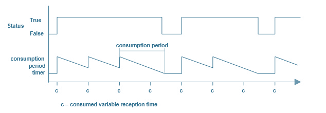
-
Consumption Period :Timeout for the promtness validity expressed in ms.
- Aperiodic's List Transfer Request
- Enable/Disable the aperiodic's list transfer requests.
- Message Emission Channel
- Enable/Disable a channel for messaging requests.
- Message Reception Channel
- Enable/Disable message reception.
Aperiodic List
- Description
- Aperiodic List item is used as container to regroup a list of Reference Variable that points to aperiodic variables (ie Variables that are not requested in the periodic window of the Scan Table).
- Parent Item
- Output Variable
- Properties
- Name
- Aperiodic List name.
- Mode
- Normal or Urgent (Priority level when the request for aperiodic transfer is made).
 Message
- Description
- This item defines an output message. The user only needs to configure the output messages. The input messages will be automatically added to the model by the app depending on the destination address of its output associated message.
NOTE : Output Message can be added to the model only if at least one Output Variable of the Station sets Message Emission Channel property. The Network must have at least two different variable IDs (minimum requirement to have a source and destination valid address). Moreover the Scan Table of the current Arbiter should have a range of time available for the aperiodic traffic to execute this type of transfer.- Parent Item
- Output Variable
- Properties
- Name
- Message name.
- Source Address
-
Segment :Source segment number.ID :Source ID
- Destination Address
-
Segment :Destination segment number.ID :Destination ID
- Channel Emission Attached
-
Type :Aperiodic or Periodic.Number :Channel number. 0 for aperiodic requests. Between 1 and 8 for periodic requests.
- Acknowledgment
- Enables/Disables the acknowledgment request when sending.
File Transfer- If sets then the message is reserved for transferring files.
 Data Rendering
- Description
- This item allows grouping several mnemonics.
- Parent Item
- Output Variable
- Output Message
- Properties
- Name
- Data rendering name.
 Mnemonic
- Description
- The Mnemonic item is used to split and format the useful data of a FIP variable or message with a personal tag name.
- Parent Item
- Data Rendering
- Properties
- Name
- Mnemonic name.
- Type
- Ascii, Bool, Float, Hexa, Int8, Int16, Int32, Int64, UInt8, UInt16, UInt32, UInt64
- Unit
- Unit of the mnemonic value.
- Start Bit
- Start bit position of the mnemonic value.
- Stop Bit
- Stop bit position of the mnemonic value.
Control - FipArbiter Device
If you have one or more EXOLIGENT's FIPArbiter device(s), you can now physically start the FIP stations you created with your model.
Bind/Unbind Device
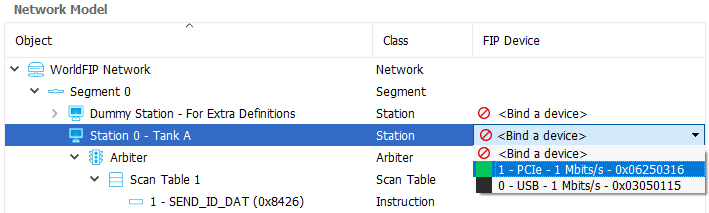
When your model is ready, you can now associate each station of the model with a FIP device.
To do this, you have two solutions:
- Manually: Click on Bind a device of the FIP Device column of the model. A drop-down list appears with all devices detected on your machine. Select the desired FIP device to bind it
- Automatically: By clicking on the Network -> Auto-Bind Devices button, the application will automatically associate the FIP devices detected on your machine with the stations of the model (in increasing order of FIP address)
Once you have binded the devices you want to drive, you can launch the connection to network by clicking on the Network -> Connect button:
![]()
Then the app creates a thread per station to drive and performs the following actions:
- Device opening
- Loading the XML configuration
- Starting the FIP communication
- Starting the bus arbiter (if present)
- Loop of actions:
- Writing the output variables of the station
- Reading the input variables of the station
- Reading and treatings the events:
- Reading the input messages
- Processing actions on a user command:
- Writing an aperiodic message
- Purging a messaging channel
- Managing the bus arbiter (Start, Stop, Continue, Toggle)
- Managing the FIP medium
- Stopping the bus arbiter and FIP communication on te loop end (thread end)
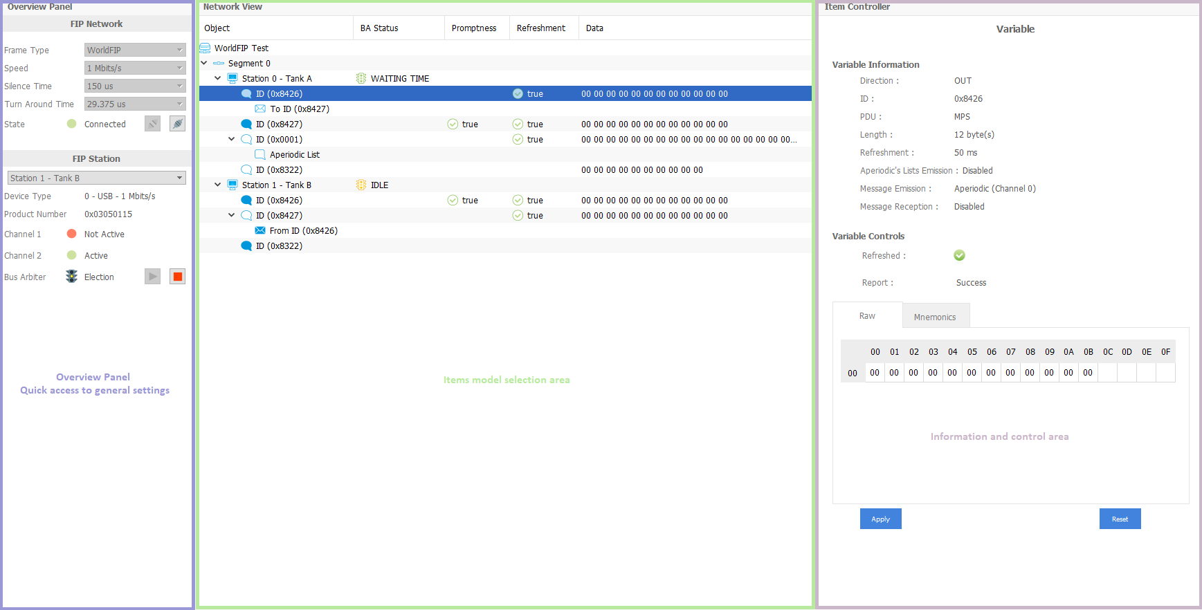
Once the connection has been successfully made, a new GUI view appears with access to the control commands for each element (item) of the FIP station.
We will now detail the different possible actions on the FIP station:
Station Management

By clicking on a station item, you can observe the above information. The view lists the properties of the station you have defined into your network model.
In addition, you have the device information that are linked to the station (Device type, Device Index, Product Number, Version, Speed, Impedance, RGB Color).
The medium information report on the state of the station channels:

- Active flags: Under certain circumstances, the FIP device may invalidate a channel (send error on channel).
- TX error flags: These send indicators are activated as soon as an error signal in transmission is detected on the line driver components of the device.
- Watchdog error flags: A send watchdog is triggered following a serious fault (line permanently busy, etc.). A user reset command is needed to reinitialize the device.
The error counters read on the device are the following:
- No Error Channel 1 / 2: Counts the number of transactions for each channel. The transaction possible are:
- ID_DAT / RP_DAT
- ID_RQ / RP_RQ
- ID_MSG / RP_MSG
- ID_MSG / RP_FIN
- ID / Silence
- Error Channel 1 / 2: Counts the number of transaction received erroneously for each channel. The type of errors detected and reported are:
- Noise detection
- Gap (Carrier Detect fall-off in middle frame)
- CRC error
- Manchester encoding fault
- Number of bits
- Error No Echo: Counts the number of transactions sent with an error for each channel (without line echo for optics only)
- Error Testp Channel 1 / 2: Counts the number of errors detected for each channel during testing of subscribers present.
Medium Controls

It's possible to send commands to the FIP channels controller embedded in the device.
- Clear Channels Errors: This command allows to delete the transmission error flags for the 2 channels (Flags TX Error 1 / 2)
- Reset Channel 1: Reinitialise channel 1 (=> Reset flag Watchdog Error 1).
- Reset Channel 2: Reinitialise channel2 (=> Reset flag Watchdog Error 2).
- Activate Channel 1 Only: Enable channel 1 & Disable channel 2.
- Activate Channel 2 Only: Enable channel 2 & Disable channel 1.
- Activate Channels 1 And 2: Enable channel 1 & 2.
Bus Arbiter Controls

![]() Start the bus arbiter (if it is stopped).
Start the bus arbiter (if it is stopped).
![]() Wake up the bus arbiter (if it is not already stopped).
Wake up the bus arbiter (if it is not already stopped).
![]() Switch from one program to another (in case the bus arbiter has two scan table set).
Switch from one program to another (in case the bus arbiter has two scan table set).
![]() Stop the bus arbiter (if it is not already stopped).
Stop the bus arbiter (if it is not already stopped).
The icon of the bus arbiter may have 3 different colors:
![]() The bus arbiter is in STOPPED state (red).
The bus arbiter is in STOPPED state (red).
![]() The bus arbiter is in STARTING or IDLE state (yellow).
The bus arbiter is in STARTING or IDLE state (yellow).
![]() The bus arbiter is active (green).
The bus arbiter is active (green).
Bus Arbiter States
For memorising purposes and for clarifying these notes the eight possible states in which an active bus arbitrator can be found are presented here:
- STOPPED: The bus arbiter is not active, nothing is transmitted by it on the network.
- STARTING: The bus arbiter is starting up. Its start delay elapses.
- IDLE: The local bus arbiter starts up and goes into election mode. Nothing is transmitted on the network during this stage. It tries to detect some activity on the network. At the end of this stage, it automatically goes into EMISSION mode if no active bus arbiter has been detected. It will remain in this state as long as the detected active bus arbiter remains active.
- MACRO END: End of macrocycle.
- SENDING ID_DAT: The bus arbiter sends ID_DAT frames.
- SENDING ID_MSG: The bus arbiter sends ID_MSG frames.
- TESTING: Presence test in progress.
- TESTING END: End of presence test.
- PENDING: The bus arbiter is suspended following a SUSPEND instruction. In this state it sends padding frames.
- APER. VAR WINDOW: The bus arbiter sends aperiodic variable traffic until the time specified in the SEND_APER has elapsed. If there is no aperiodic variable traffic it automatically goes to the next instruction of the macrocycle.
- APER. MSG WINDOW: The bus arbiter sends aperiodic message traffic until the time specified in the SEND_MSG instruction has elapsed. If there is no aperiodic message traffic, it automatically goes to the next instruction in the macrocycle.
- WAITING TIME: The bus arbiter waits until the specific time in the WAIT instruction has elapsed. In this state it sends padding frames.
- WAITING SYNC.: External resynchronization in progress.
- WAITING SYNC. SILENT: External resynchronization in progress.
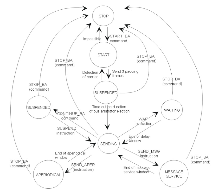
In order to understand the behavior of the bus arbiter, here is a summary diagram of states and possible transitions:
Writing an output variable
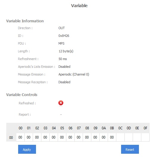
By clicking on an output variable item, you can observe the above information. The view lists the properties of the variable you have defined into your network model.
The item control consists of a hexadecimal table representing the useful data frame of the variable. This table can be updated and sent to the FIP network by clicking the Apply button.
To reset all values in the table, click on Reset button.
For output variable with the refreshment set, a Refreshed flag appears.
The Report tag indicates the status of the last write command.
Reading an input variable
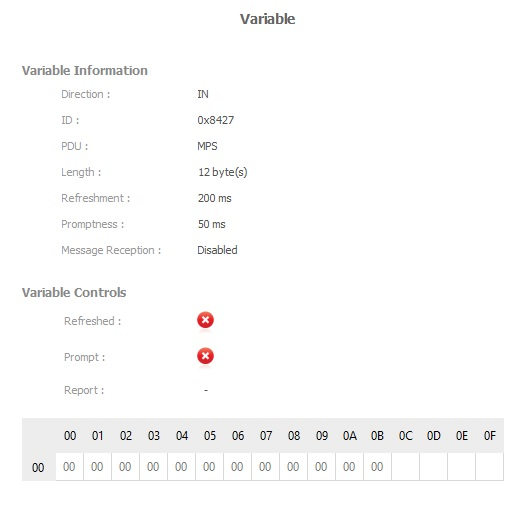
By clicking on an input variable item, you can observe the above information. The view lists the properties of the variable you have defined into your network model.
The item control consists of a hexadecimal table in read-only representing the useful data frame of the variable.
For an input variable with the production status set, a Refreshed flag appears.
The Prompt flag is updated during the reading of the variable in the app thread.
The Report tag indicates the status of the last read command.
Sending an Aperiodic List
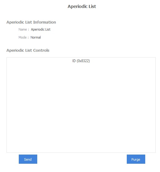
Send button allows to make a request for the transfer of a list of variables via the aperiodic send service. The transfer type is determined by the Mode property (Urgent or Normal).
Purge button allows to reset the aperiodic request queue to 0.
Writing an Output Message
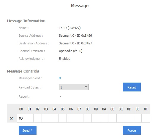
By clicking on an output message item, you can observe the above information. The view lists the properties of the message you have defined into your network model.
The item control consists of a hexadecimal table representing the useful data frame of the message. The message size is defined by the user through the Payload Bytes combo-box (Up to 256 bytes).
To reset all values in the table, click on Reset button.
Once the table is filled with the desired value, the message can be sent to the FIP network by clicking the Send button.
Purge button allows to reset the message request queue to 0.
The FIP device has 9 FIFO queues for message send:
- Channel 0: Aperiodic messaging
- Channel 1 to channel 8: Periodic messaging
On the Send command, the FIP device searches for the corresponding send FIFO (Channel Emission tag), checks that it is not full (Up to 24 messages per sending FIFO) and transfers the information making up the message to the database. Then the message will be published on the FIP network if the active bus arbiter is correctly configured.
The Report tag indicates the status of the last write command.
Reading an Input Message
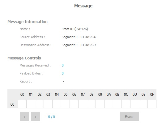
By clicking on an input message item, you can observe the above information. The view lists the properties of the message you have defined into your network model.
The item control consists of a hexadecimal table in read-only representing the useful data frame of the message.
The right and left arrow buttons allows to browse message history.
Erase button deletes the history of reception of the messages.
The Report tag indicates the status of the last read command.
Sending a file
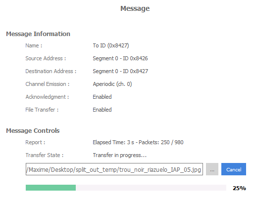
By clicking on an output message item with File Transfer option enabled, you can observe the above information.
Select the file you wish to send with the path button and click on send button to start the transfer. If a station is listening, a progress bar should be displayed to inform you about the progress of the exchange.
Receiving a file
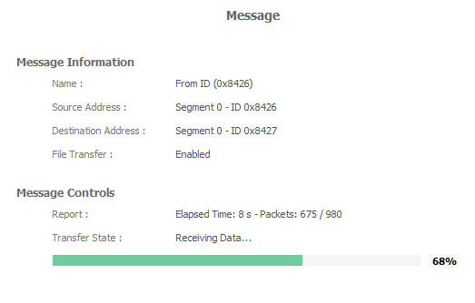
Receiving a file is done automatically. If a transfer is in progress, you can see the progress of the exchange by clicking on the input message item concerned.
The directory for receiving files is set in the following section of FipLabs app: Options Tab -> General -> File Transfer - Reception Directory.
Note : By default the directory path is C:/Users/{UserName}/Documents/Exoligent/FipLabs/Downloads.